Many Americans tend to ridicule the British Whitworth system because the size stamped on the jaw refers to the size of the bolt shank instead of the across-the-flat (A/F) measurements of the bolt head or nut.

In fact, the Whitworth system is very logical. After all, in any given engineering application, the diameter of the bolt shank is a given but, within limits, the actual size of the nut or bolt head is completely arbitrary. For that matter, we classify nuts and bolts by the shank size, not by the measurement across the flats. For instance, you know you need to fasten a a nut on a 1⁄2" bolt, so why not have a wrench that says 1⁄2, even if the nut or bolt head is larger than this? Instead, unless you're really experienced with the American system, you take your 1⁄2" bolt over to the tool box and dig around for the proper across-the-flats fractional size that will fit it, trying on smaller and larger sizes until you find the correct size. Or, if you prefer, you can do the math. The convention in the American system is as follows: for bolt diameters (D) from ¼" to ⅝" inclusive, width across the flats is determined by the formula 11⁄2 D + 1⁄16. For bolts larger than 5⁄8" in diameter, the formula is simpler: 11⁄2 D. Now, isn't Whitworth really simpler?
So, how did we end up like this? In the beginning, manufacturers made threaded fasteners to their own unique sizes. As parts interchangeability became increasingly necessary, engineers looked to standardize. The first to do so was Sir Joseph Whitworth (1803-1887) who presented his system in Great Britain in 1841. Initially, he proposed only a coarse thread (which became known as British Standard Whitworth, or BSW or just plain W). Much later (67 years later, actually, in 1908) a fine thread was added: British Standard Fine (BSF or BS). For any given bolt shank diameter, the BSF series used a smaller nut than the BSW series. Hence, most British wrenches carry two markings on each jaw, since the same jaw opening will fit a bolt head or nut on a bolt on a given diameter of bolt with a coarse thread, and the bolt head or nut on the next size greater diameter of bolt with a fine thread. (I have to admit, this is confusing!)


This made for rather a cluttered appearance on the wrench jaws or body, as the examples below demonstrate.

(Of course, one some British-made wrenches, the manufacturer only forged the fraction on the jaws, omitting any reference to Whitworth. This makes sense since, within the U.K., why would you need to distinguish it from the U.S. system which, after all, didn't come along until decades later. It would be just taken for granted that 1/2 on the wrench meant 1/2 Whitworth.) Below, several such wrenches by R.T. Shelley:

Similarly, Whitworth wrenches made by the German firm Stahlwille, presumably for the British market:

There seem to be several explanations for the difference in British wrench sizes based on thread pitch. By the time the Whitworth Fine series was introduced, nuts could be made smaller due to better metallurgy. In addition, a finer thread meant more torque could be applied (as there were more threads to bear against each other), so again, a smaller nut would suffice. Finally, manufacturing had progressed beyond the production of huge machines like locomotives (where you could afford to have a yard of open space around a fastener) to more sophisticated and compact devices like automobiles and aircraft in which space and weight was at a premium. So, on a given diameter of bolt, nuts on the fine (BSF) series were always smaller than on the coarse (BSW) series.
Across the pond, things were slower to get going. William Sellers (1824-1905), a manufacturer of machine tools in Philadelphia, was well aware of what Whitworth had accomplished in Britain. Sellers persuaded the Franklin Institute in that city to set up committee for the purpose of investigating a standard thread form series. (As an aside, to Sellers we owe the color “machinery gray.” When others were decorating their machinery, he insisted on painting his a uniform light gray, in order not to obscure the functions of the parts.) In 1884 (43 years after Britain had adopted the Whitworth system, and 3 years before Whitworth's death at the age of 84) the American committee recommended the adoption of many of the thread forms which had been proposed by Mr. Sellers, which became known as the "Franklin" thread series, the “Sellers Standard” and ultimately the United States Standard (USS) for coarse threads after it was adopted by the U.S. Navy. However, aside from some minor variations in the shape and angle of the thread form, the thread pitch was almost identical to Whitworth's.

Even though Sellers was a major American manufacturer (or perhaps because of this) adoption of his system by other manufacturers was slow. As in Great Britain, a need for finer threads was driven by the development of the automobile and aircraft industry. In 1906, the Association of Licensed Automobile Manufacturers developed such a series which became known as the A.L.A.M Standard or sometimes the automobile standard. In 1911, this was placed in the custody of the Society of Automotive Engineers, which then became the SAE standard series of fine-threads. Coincidentally, yet another manufacturing organization set its own standards for cap screws: the Bolt, Nut and Rivet Manufacturer's Association. (Given the confusion that reigned because of these competing systems during WWI, in 1918 the National Screw Thread Commission was jointly sponsored by the SAE and the American Society of Mechanical Engineers. Ten years later, the US Standard was renamed the American National form, with the coarse threads recommended for general engineering use, and the fine threads for "for general use in automotive & aircraft work, where design requires both strength and reduction in weight." It wasn't until 1933 that the old USS was renamed National Coarse, and the old SAE thread officially became National Fine.)
Even today, there remain different American organizations who maintain their own standards:

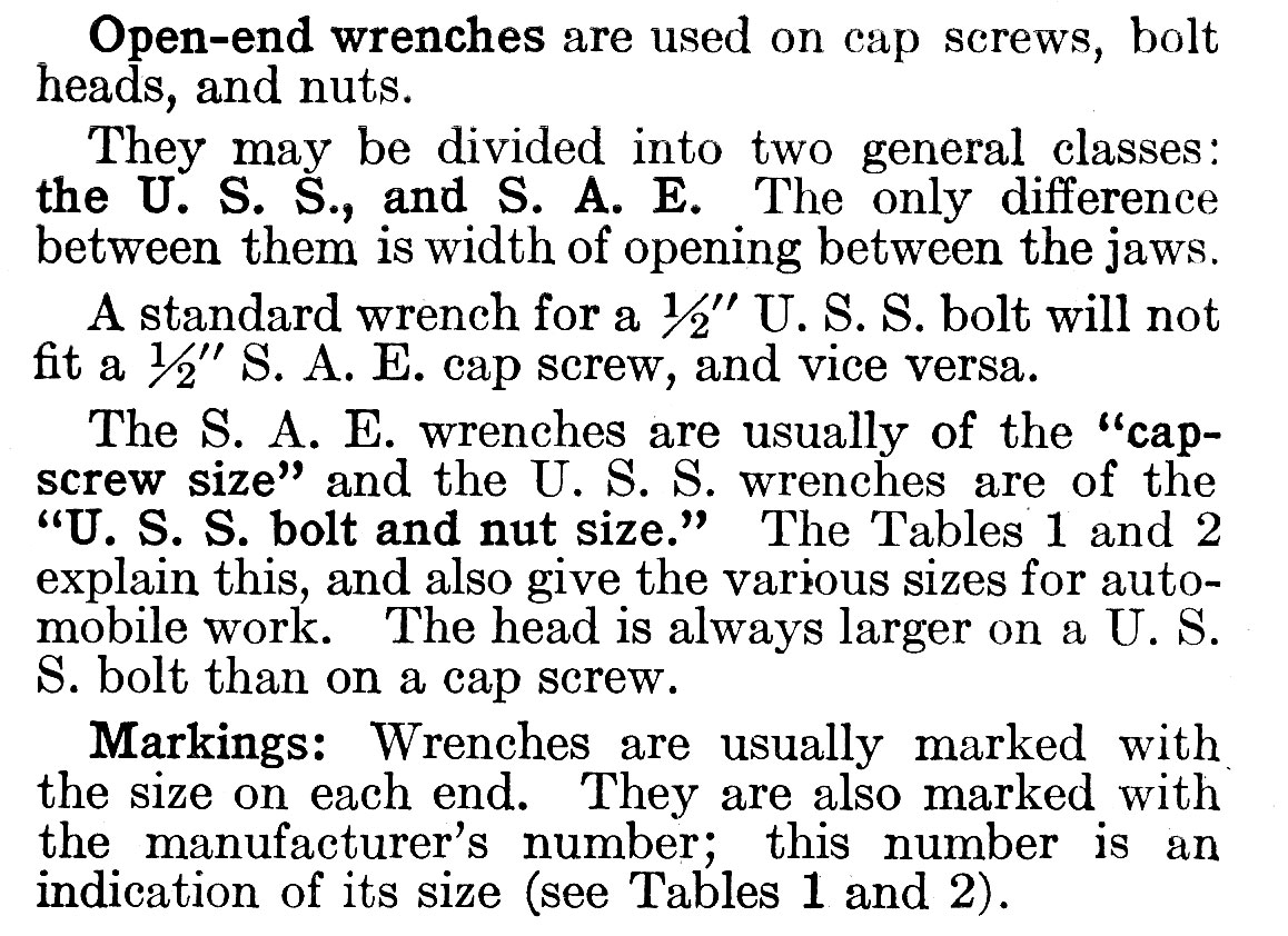
Of special interest, note that in the 1926 table below, USS (coarse-thread) bolts use a larger A/F size of wrench than SAE (fine-thread) bolts of the same diameter, just as in the Whitworth system:


Another Williams wrench, this time stamped 1/4 and 5/16, but measuring 1/2" and 19/32" A/F (Note that the top wrench is also stamped 23 and the one below 25; more on this later):

Here's another made by Whitman & Barnes, stamped 3/16 and 1/4, but actually measuring 13/32" and 1/2" A/F, indicating that the wrench size is USS:


Next, a wrench stamped SAE, with ends marked 1/4 and 5/16. On my vernier, the actual openings are .440" and .515" which would be a sloppy fit for a 7/16" and 1/2" bolt head. In the SAE (fine-thread) system, a 1/4" diameter bolt would take a 7/16" A/F wrench, and a 5/16" bolt would take a 1/2" A/F wrench. So again, this wrench is stamped for the bolt diameter, not for the A/F sizes.

Finally, another wrench stamped SAE, with ends marked 3/8 and 7/16. In fact, the 3/8 end measures .570 inch (instead of .375") and the 7/16 end measures .640 inch (instead of .4375). Again, a sloppy fit on a 9/16" and 5/8" A/F bolt head. These are exactly the A/F dimensions specified under the SAE criteria for these diameters of bolts.

So, it's clear that at some point, American wrench sizes followed the Whitworth system, although the actual A/F dimensions for each bolt diameter in the two series were different:
Perhaps to try to get around all of this confusion, beginning with J.H. Williams, various tool manufacturers began stamping wrenches with their own code numbers. Everyone who likes old tools has come across these old wrenches marked only by a cryptic number. Alloy Artifacts has the best accounting of this system, which was referred to as "Industry Standard Numbers." Each number related to sizes for bolts from the USS, SAE and Hex Cap series. Below, some by Billings, Vlchek and others:

Even today, there remain different American organizations who maintain their own standards:

Back to wrench sizes. In his proposal, Sellers also included a rule for how to proportion hex nuts, from 1/4" to 6 inches in bolt diameter. It would seem that American manufacturers were quicker to adopt his thread forms than to endorse his ideas for the size of square and hexagonal nuts and bolt heads. On top of that, the different American thread standards also came with different standards about the size of the nuts and bolt heads and cap screws:
 |
| A.L. Dyke. Dyke's Automobile and Gasoline Engine Encyclopedia. Chicago: The Goodheart-Willcox Company, Inc., 1941. |
Of special interest, note that in the 1926 table below, USS (coarse-thread) bolts use a larger A/F size of wrench than SAE (fine-thread) bolts of the same diameter, just as in the Whitworth system:
 | |
|
To add to the fog, here are some more tables taken from A.L. Dyke. Dyke's Automobile and Gasoline Engine Encyclopedia. Chicago: The Goodheart-Willcox Company, Inc., 1941:


From what I can determine, originally sizes marked on wrenches in the Seller's system were also defined by the shank diameter of the bolt, and not by A/F dimensions. To support this, I offer the following wrenches from my collection:

From what I can determine, originally sizes marked on wrenches in the Seller's system were also defined by the shank diameter of the bolt, and not by A/F dimensions. To support this, I offer the following wrenches from my collection:
First is an American-made J.H. Williams wrench stamped 3/16 and 1/4. However, these are not across-the-flat measurements, as the 3/16 opening actually measures about 13/32") and the 1/4 opening measures about 1/2"). In the original USS (coarse-thread) system,a 3/16" bolt would take a 13/32" A/F wrench and a 1/4" bolt would take a 1/2" A/F wrench. So, this American wrench has jaw markings that clearly refer to bolt diameter, not to A/F dimensions.


Here's another made by Whitman & Barnes, stamped 3/16 and 1/4, but actually measuring 13/32" and 1/2" A/F, indicating that the wrench size is USS:

Next, a wrench stamped SAE, with ends marked 1/4 and 5/16. On my vernier, the actual openings are .440" and .515" which would be a sloppy fit for a 7/16" and 1/2" bolt head. In the SAE (fine-thread) system, a 1/4" diameter bolt would take a 7/16" A/F wrench, and a 5/16" bolt would take a 1/2" A/F wrench. So again, this wrench is stamped for the bolt diameter, not for the A/F sizes.


 |
| Machinery's Handbook for Machine Shop and Drafting-Room. 8th Edition. New York The Industrial Press, 1930. |


This happened in Canada, too. Below, a Gray 723 whose jaws actually measure 3/8" and 7/16" A/F:

I'd be interested to know how mechanics back in the day used to deal with this. Did you ask, "Hey, bring me over the 723 wrench?"
Below, again from A.L. Dyke. Dyke's Automobile and Gasoline Engine Encyclopedia. Chicago: The Goodheart-Willcox Company, Inc., 1941:


Below, again from A.L. Dyke. Dyke's Automobile and Gasoline Engine Encyclopedia. Chicago: The Goodheart-Willcox Company, Inc., 1941:
As mentioned above, yet another screw and bolt standard had been promulgated by the American hardware manufacturers, and I think may have been standardized by the Bolt, Nut and Rivet Manufacturer's Association. This pertained to cap screws, and was indicated on wrenches by a small stamped hexagon followed by the letter C, or by the abbreviation "Cap." Below, from a Billings 1400 wrench:


Below is a Bonney wrench using this system. On one end, it's marked 5/16 CAP and measures .515" or slightly more than 1/2" A/F. On the other end, it's marked 3/16 ⯃C ("3/16 Hex cap") and measures .390" or roughly 3/8" A/F.


Below is a Bonney wrench using this system. On one end, it's marked 5/16 CAP and measures .515" or slightly more than 1/2" A/F. On the other end, it's marked 3/16 ⯃C ("3/16 Hex cap") and measures .390" or roughly 3/8" A/F.

Some wrenches did double or even triple duty by combining measurements from more than one standard. The Gray wrench below is stamped 31 on one end and 5/8 ⯃C and and 1/2 USS (actual measurement .900" or 7/8") on the other.


Below, a McKinnon wrench carrying designations from all three measuring systems:


Below, several Kraeuter wrenches which follow the same pattern:


On the wrench above, one end is stamped 5/8 OPENING and 7/16 US (actual measurement .640" or 5/8") and A 1820. The other end is stamped 9/16 OPENING and 3/8 ⯃C (actual measurement .580" or 9/16").
Finally, the Kraeuter wrench below is marked 25 on the shank.


It's marked 19/32" OPEN and 5/16 USS and what looks like 1619 below that. That end measures .615" (19/32"). The markings on the opposite end are very worn, I can only make out 5/16 ⯃C, for an opening that is .530" wide, or 1/2". These A/F dimensions are accurate for USS and Hex Cap fasteners of these bolt diameters. The 1619 may be Kraueter's own Industry Standard Number.
Not to be left out, a combination Hex cap and SAE wrench by Williams. The actual A/F dimension is 9/16".

Not to be left out, a combination Hex cap and SAE wrench by Williams. The actual A/F dimension is 9/16".

 |
| A.L. Dyke. Dyke's Automobile and Gasoline Engine Encyclopedia. Chicago: The Goodheart-Willcox Company, Inc., 1941. |
Confusion continued. See the table below, in which a 5/16" USS bolt is expected to have a head whose width across the flats is 11/32".

Below, nut sizes after the USS system was changed to the American Standard in 1928:
 |
| Machinery's Handbook. 8th Edition. New York: The Industrial Press, 1930. |
As you can see from the footnote above, in 1927 the maximum width A/F for 5/8" nuts was increased from 15/16" to 1". It also looks like adjustments were made at that time to eliminate widths to 32nd of an inch.
So, it looks like the seven wrenches with A/F markings in 32nds of an inch (11, 13, 15, 19, 21, 25, 31) disappeared after this time. These odd-ball wrenches (and sockets) continue to turn up from time-to-time in my neck of the woods:
 |
| A.L. Dyke. Dyke's Automobile and Gasoline Engine Encyclopedia. Chicago: The Goodheart-Willcox Company, Inc., 1941. |
So, it looks like the seven wrenches with A/F markings in 32nds of an inch (11, 13, 15, 19, 21, 25, 31) disappeared after this time. These odd-ball wrenches (and sockets) continue to turn up from time-to-time in my neck of the woods:

The situation with these competing standards actually got to the point where Bolt's Antique Tool Museum could create a display of seventeen wrenches, all marked 1/2", with 19 different identifications and sizes!
In the late 1920's, most American tool manufacturers finally moved to stamping A/F sizes on their wrenches.
To help things out, some tool makers like Gray put the new A/F dimensions on the wrench jaws along with the old USS ones:

When these were made in England, they were stamped "A/F" to indicate that the wrench size measurements were based on the across-the-flats dimension of the jaws, and not the diameter of the bolt (i.e., not Whitworth):
 |
| William H. Crouse. Automotive Mechanics, 4th Edition. McGraw-Hill Book Co., Inc., 1960. |
To help things out, some tool makers like Gray put the new A/F dimensions on the wrench jaws along with the old USS ones:

When these were made in England, they were stamped "A/F" to indicate that the wrench size measurements were based on the across-the-flats dimension of the jaws, and not the diameter of the bolt (i.e., not Whitworth):

Even after this time, not all tool makers transitioned entirely to the fractional A/F wrench sizes. Below, a Billings Vitalloy wrench marked only M1021. Billings didn't introduce the Vitalloy trademark until 1937.

Similarly, the Ford Motor Company continued to make wrenches without any size markings for use in its tool kits:

Only one of the wrenches above has any identification stamped on:

This was a 9/16" X 5/8" (A/F) wrench for Model A cars made in early 1928, as the curly Ford logo wasn't stamped on wrenches after April of that year. (The MH logo indicates that the wrench was made for Ford by McKaig-Hatch of Buffalo, just one of Ford's tool suppliers.) However, the same wrench with no fractional markings continued to be available for the 1939-40 9N tractors.
Below, a Dodge Brothers wrench used on their vehicles between 1918 and 1929. Although it measures 7/16" and 1/2" A/F, the wrench itself has no markings.

Ford and Dodge were clearly big enough to do whatever they pleased.
Finally, the Canadian-made McKinnon wrench below demonstrates that even today's convention of stamping the size of a wrench at each end wasn't always customary (the wrench is 3/8 USS on one end, and 716 USS on the other):

Anyway, the foregoing clearly indicates that any American contempt for the Whitworth system is entirely misplaced. The American system began as a very close copy of the Whitworth standards and ultimately became even more complicated and confusing before finally ending up in its present form.
Minor changes to both the American and Whitworth systems continued to occur after this. According to Wikipedia, in World War II the size of the Whitworth hexagon was reduced to the same size as the equivalent BSF hexagon purely to save metal during the war, and this remained in effect following the war. Wrenches made to reflect this change are simply marked BS, to fit both the later BSW and BSF nuts and bolt heads.


Some tool manufacturers made the attempt to mark the same wrench with approximate sizes of two or even three of the competing systems (SAE, Whitworth and metric). To see some examples, visit my earlier post: One size does not fit all.
In 1948, an agreement among Great Britain, the U.S. and Canada resulted in today's "Unified" thread series. Interestingly, the U.S. military didn't adopt it until 1957, and the British Standards Institution didn't recommend abandoning the Whitworth system until 1965. (In fact, they preferred the ISO metric thread, with the ISO inch (Unified) thread being their second choice.) Today, the Whitworth system has all but disappeared in the U.K.
Still, for those of us who still play around with these old tools and their associated machinery, it's important to know which wrench will fit what. Below, a very handy table courtesy of the King Dick tool catalogue.
Still, for those of us who still play around with these old tools and their associated machinery, it's important to know which wrench will fit what. Below, a very handy table courtesy of the King Dick tool catalogue.

If any readers would like a larger version for handy reference, I've uploaded a pdf here.
10 comments:
A remarkable piece of research. Thank you.
I've read somewhere that Whitworth's 55 degree threadform was actually the superior choice to the 60 degree form we ended up with. I'm not qualified to judge that, but it's a tantalizing notion; one is put in mind of the Beta/VHS confrontation.
Sellers supposedly chose 60 degrees because it was easier to measure than the 55 degree Whitworth thread form. (Anyone who has used a screw thread gauge to set up a thread-cutting tool on a lathe would know this to be nonsense.) In the Whitworth system, the roots and crests of the thread were rounded; in the Seller's system, the roots and crests were flattened. The Seller's form is easier to turn on a lathe. We know now that sharp angles, such as those formed between a flat thread root and the thread itself, are stress risers--they concentrate stress and are more likely to shear. So, Whitworth's rounded thread form was stronger for this reason.
Great blog article. Thanks
good blog.thanks for sharing about The evolution of standard wrench sizes.it is very useful for me .
There remains a couple of threads used in Britain. BA, small sized and used in the model making industry a lot and Model Engineering Thread, which boasted 40 TPI whatever the diameter!
In the UK, we also have Acme thread, Brass thread, Cycle thread, the worldwide Pipe thread and I have heard reference to 'a watch thread', but I know of no co-relation between the thread size and the dimension across the flats of the respective nuts.
There is also some specific firearm- manufacturer threads...
It's endless!
Excellent; a very informative (and accurate)article; thank you.
The diameter of the bolt or rivet was the most important consideration when the strength of a structure was concerned. Distance across the flats had little effect on the stretngth of a fastening ... until it looked ridiculous.
As I recall from my college days (late 1940s) Whitworth used geometry to arrive at fifty five degrees for the thread angle - again it was strength that was the main concern here.
Bhalla fasteners
Best quality bolts and nuts manufacturers in india
Bhalla Fasteners, Ludhiana are super brand quality bolts and nuts manufacturers in India, with skilled and qualified teams providing quality assurance.Read more..
Sweet thanks
Post a Comment